Motivation
The investigation of the antenna in a mag
Motivation
The investigation of the antenna in a magnetoplasma environment is motivated by the interest of studying the particle and wave interaction in the upper atmosphere, which is important in understanding the mechanism of the precipitation of energetic particles. This work will help to design and optimize the antenna performance to maximize the VLF waves radiated into the magnetosphere.
Past Modeling Efforts
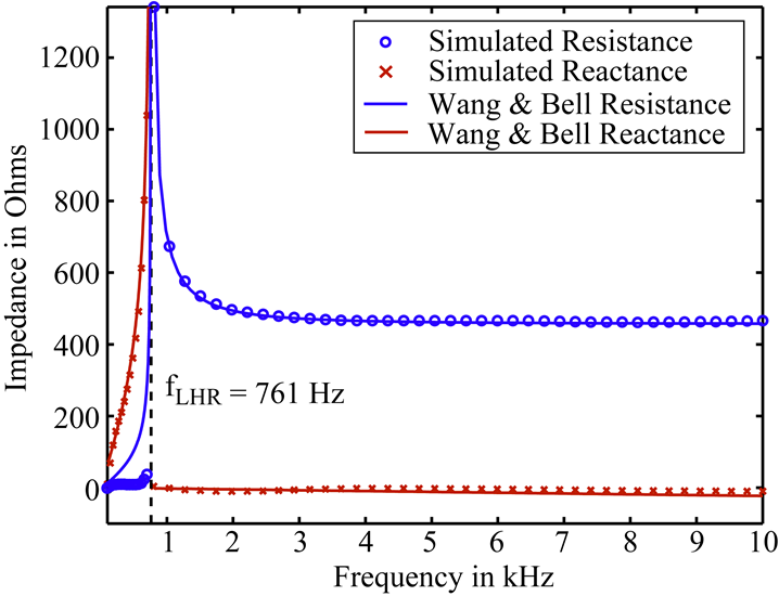
The research of the coupling between the antenna and the magnetized plasma can be traced to 1960s. In 1964, Balmain performed some of the first analytical research on electric dipole antennas in cold plasmas (Balmain, 1964). In 1969, Wang and Bell in our group derived closed-form analytical expressions for the radiation resistance of electric dipole antennas operating in a cold magnetoplasma for frequencies above ![]() (Lower Hybrid Resonance frequency) using a full-wave solution (Wang and Bell, 1969). From 1970 to 1972, Wang and Bell extended work for frequencies below
(Lower Hybrid Resonance frequency) using a full-wave solution (Wang and Bell, 1969). From 1970 to 1972, Wang and Bell extended work for frequencies below ![]() (Wang and Bell, 1970), derived formulas for the radiation patterns of arbitrarily oriented electric and magnetic dipoles in a cold collisionless magnetoplasma (Wang and Bell, 1972a), and examined the radiation characteristics of an electric dipole at VLF frequencies in a linearized warm plasma magnetoplasma by adding a finite electron temperature effect incorporated through addition of a scalar pressure term in the cold plasma equations (Wang and Bell, 1972b).
(Wang and Bell, 1970), derived formulas for the radiation patterns of arbitrarily oriented electric and magnetic dipoles in a cold collisionless magnetoplasma (Wang and Bell, 1972a), and examined the radiation characteristics of an electric dipole at VLF frequencies in a linearized warm plasma magnetoplasma by adding a finite electron temperature effect incorporated through addition of a scalar pressure term in the cold plasma equations (Wang and Bell, 1972b).
Early research on the plasma sheath effects on the properties of dipole antennas includes Mlodnosky and Garriott who used small signal analysis coupled with a fixed-capacitor analogy to derive closed-form expressions for the sheath radius, capacitance and resistance of a VLF dipole antenna (Mlodnosky and
Garriott, 1963). This work is extended by Shkarofsky to include large signal excitation and the effects of drift motion of the antenna at orbit speed (Shkarofsky, 1972). Baker et al. incorporate a DC bias into the model resulting from spacecraft charging between the antenna and the satellite body (Baker et al., 1973). More recently, Song et al. applied linearized fluid theory based on Shkarofsky to analytically derive the terminal properties and sheath characteristics surrounding electrically short dipole antennas at large drive voltages relative to the ambient plasma potential (Song et al., 2007). Chevalier developed a 3-D parallel FDTD code to determine the current distribution and terminal impedance of electric dipole antennas in a cold magnetoplasma (Chevalier et al., 2008), and a 3-D nonlinear multi-moment hydrodynamic code to determine the sheath effects on near-field characteristics of electric dipole antennas (Chevalier et al., 2010).
Antenna-In-Plasma (AIP) Code
Recently, Timothy Chevalier in our group developed a fully parallel 3-D finite-difference time-domain (FDTD) code for the simulation of electromagnetic waves in cold magnetized plasmas with arbitrary material boundaries. The code calculates the current distribution and the input impedance of the antenna in the inner magnetosphere. The variation of the input impedance as a function of the drive frequency is compared with existing analytical models and experiments conducted by UCLA.
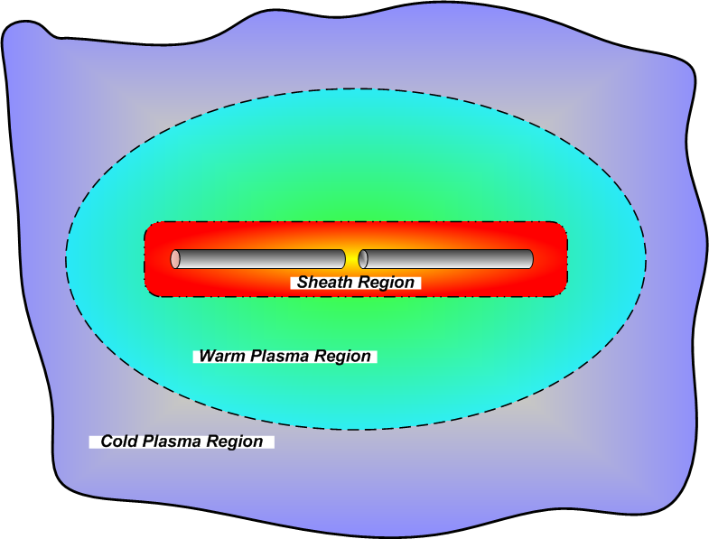
Timothy Chevalier also developed a fully parallel 3-D nonlinear multi-moment hydrodynamic code for the simulation of electrostatic sheath formation in warm unbounded collisionless magnetized plasmas. The code can be used to determine the effects of the plasma sheath on the near field characteristics of electric dipole antennas. More detailed description of the AIP code can be found in Timothy Chevalier’s PhD thesis (Chevalier, 2007).
Tuning the Antenna
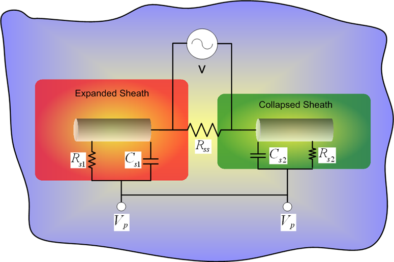
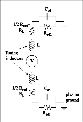
Present work focuses on tuning the antenna to obtain maximum radiated wave power immersed in the plasma. This work is based on an equivalent circuit model and the existing analytical models. A differential equation of the equivalent circuit is derived and solved to indicate the optimum inductance value for compensating the sheath capacitance.
Based on recent numerical results of AIP code, the existing analytical models of the sheath capacitance and sheath conductance are improved. In the modified model, correction factors are added to the sheath radius and the thermal effect of the particles are included. The modified model combined with the circuit model of the antenna is able to calculate the near field characteristics of the antenna within 10% deviation compared with the numerical codes for different drive voltages. At present, more advanced tuning strategies are being developed based on the modified analytical models.
Acknowledgements
This research was supported by the Air Force Office of Scientific Research and by Sequoia Technologies.
Bibliography
-
Baker, D., H. Weil, and L. Bearce (1973), Impedance and large signal
excitation of satellite-borne antennas in the ionosphere, IEEE
Transactions on Antennas and Propagation, 21, 672-679,
doi:
rm10.1109/TAP.1973.1140550.
-
Balmain, K. (1964), The impedance of a short dipole antenna in a
magnetoplasma, IEEE Transactions on Antennas and Propagation,
12, 605-617, doi:
rm10.1109/TAP.1964.1138278.
-
Chevalier, T. W. (2007), Near-field characteristics of electric dipole
antennas in the inner magnetosphere, Ph.D. thesis, Stanford Univ., Stanford,
Calif.
-
Chevalier, T. W., U. S. Inan, and T. F. Bell (2008), Terminal Impedance
and Antenna Current Distribution of a VLF Electric Dipole in the Inner
Magnetosphere, IEEE Transactions on Antennas and Propagation,
56, 2454-2468, doi:
rm10.1109/TAP.2008.927497.
-
Chevalier, T. W., U. S. Inan, and T. F. Bell (2010), Fluid simulation of
the collisionless plasma sheath surrounding an electric dipole antenna in the
inner magnetosphere, Radio Science, 45, 1010-+,
doi:
rm10.1029/2008RS003843.
-
Mlodnosky, R. F., and O. K. Garriott (1963), The v.l.f. admittance of a
dipole in the lower ionosphere, in The Ionosphere, edited by
A. C. Stickland, pp. 484-+.
-
Shkarofsky, I. P. (1972), Nonlinear sheath admittance, currents, and charges
associated with high peak voltage drive on a VLF/ELF dipole antenna moving in
the ionosphere, Radio Science, 7, 503-+,
doi:
rm10.1029/RS007i004p00503.
-
Song, P., B. W. Reinisch, V. Paznukhov, G. Sales, D. Cooke, J. Tu,
X. Huang, K. Bibl, and I. Galkin (2007), High-voltage antenna-plasma
interaction in whistler wave transmission: Plasma sheath effects,
Journal of Geophysical Research (Space Physics), 112,
3205-+, doi:
rm10.1029/2006JA011683.
-
Wang, T. N. C., and T. F. Bell (1969), Radiation resistance of a short
dipole immersed in a cold magnetoionic medium, Radio Science,
4, 167-+, doi:
rm10.1029/RS004i002p00167.
-
Wang, T. N. C., and T. F. Bell (1970), On VLF radiation resistance of an
electric dipole in a cold magnetoplasma, Radio Science, 5,
605-+, doi:
rm10.1029/RS005i003p00605.
-
Wang, T. N. C., and T. F. Bell (1972a), VLF/ELF Radiation
Patterns of Arbitrarily Oriented Electric and Magnetic Dipoles in a Cold
Lossless Multicomponent Magnetoplasma, J. Geophys. Res.,
77, 1174-1189, doi:
rm10.1029/JA077i007p01174.
-
Wang, T. N. C., and T. F. Bell (1972b), VLF/ELF input
impedance of an arbitrarily oriented loop antenna in a cold collisionless
multicomponent magnetoplasma, IEEE Transactions on Antennas and
Propagation, 20, 394-398, doi:
rm10.1109/TAP.1972.1140212.