Introduction
Stanford VLF research is primarily interested in signals with frequencies in the range of 300Hz to 30kHz. This spectrum includes man-made navigation signals, as well as natural phenomenon such as sferics and whistlers, which are generated by lightning. Off the shelf electronics are not well suited to capture these signals, so the Stanford VLF group has developed it’s own specialized receiver systems. These systems consist of an analog front-end, analog to digital converters, and data storage.
Introduction
Stanford VLF research is primarily interested in signals with frequencies in the range of 300Hz to 30kHz. This spectrum includes man-made navigation signals, as well as natural phenomenon such as sferics and whistlers, which are generated by lightning. Off the shelf electronics are not well suited to capture these signals, so the Stanford VLF group has developed it’s own specialized receiver systems. These systems consist of an analog front-end, analog to digital converters, and data storage. The analog front-end limits the performance of the overall system, making its design critical.
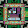
The VLF receiver front-end consists of three parts. The first is the antenna, which is typically a loop antenna used to sense the magnetic field. This is different from a standard radio dipole antenna that senses the electric field. The second part is the input transformer. Its function is to match the antenna impedance to the third part of the system, the front-end amplifier. The amplifier amplifies and filters the small signal so it can then be digitized and stored. Due to the nature of the magnetic sensing receiver, a standard front-end amplifier isn’t suitable. Instead, a custom architecture is required to satisfy the unique set of performance requirements. The chip layout for the current VLF receiver front-end amplifier is shown in Figure 1.
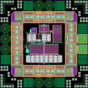
Figure 1. Stanford VLF receiver front-end amplifier IC layout.
Design Challenges
Power
Stanford VLF receivers are deployed throughout the world, including remote locations with no access to the power grid. In these cases, the receivers run on battery power. Clearly it’s important that the receiver system consume as little power as possible to ensure that it is able to run uninterrupted for long periods of time. One extreme example is the VLF receiver deployed at the South Pole. This particular receiver must be ultra low-power because it is only feasible to visit the site once per year to collect data and replace the batteries.
Noise
Noise is a critical concern for the front-end amplifier because it limits the overall noise performance of the receiver system. This difficulty is compounded by the extremely small magnetic signals that are being detected, often on the order of a femtotesla (1×10-15 Tesla). Even the smallest amount of excess noise could corrupt the signal. The noise performance of the front-end depends not only on the front-end amplifier, but also on the antenna and transformer characteristics. This makes designing for good noise performance challenging and results in an interesting optimization problem between several competing constraints.
Distortion
The VLF receivers are broadband systems, in the sense that they cover the entire VLF spectrum from approximately 300Hz to 30kHz. This means that not only will the desired signal be received, but also undesired interfering signals that happen to fall in the VLF band. These include VLF transmitters run by the Navy and various navigation related signals. If the interfering signals are strong, they can overdrive the front-end amplifier, which causes distortion and can overpower the desired weaker signals. To combat this problem the linearity and dynamic range of the front-end are key design concerns.
Temperature Stability
With the VLF receiver deployed in a variety of climates, it’s important that the front-end work properly over a wide range of temperature. At the South Pole, for example, temperatures often reach -70° Celsius. This extreme exceeds what most standard electronics are designed to withstand. To account for this, previous front-end designs utilized manual tuning to adjust the front-end amplifier depending on the expected temperature. However, this is troublesome if the temperature varies significantly. For this reason, auto-tuning schemes are now employed to automatically adjust for extreme temperatures with the added benefit of compensating for component drift, which may occur over time.
More Info
- Magnetic Sensor Design for Femtotesla Low-Frequency Signals. Sarah K. Harriman.
- The Design of Broad-Band VLF Receivers with Air-Core Loop Antennas. Evans W. Paschal.
Acknowledgements
This research is supported by the Stanford Center for Position, Navigation and Time (SCPNT).